Influences in practical use
When you consider the calibration values of a flowmeter, ideally they should not deviate from the measuring values in the application. In fact, there are a number of influencing variables which require great care when installing in the application given the wide variety of flowmeters and measuring principles.
Inlet and outlet sections
Only by closely analysing the application can undetected systematic measurement errors be reduced from the outset. The inlet conditions of the flowmeter represents one of the main influencing variables on the measurement result.
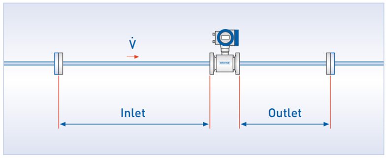
Inlet and outlet sections refer to the section of a straight tube before and after the measuring device, not including built-ins (interferences) such as elbows, valves, ball valves etc. It can also be referred to as an unimpeded or free inlet section. This is usually expressed in a whole number multiple of the pipe diameter, e.g. a 10D inlet section on a DN 200 pipe corresponds to a length of 2 m. Observing the inlet and outlet sections of different lengths is sometimes necessary to reduce influences on the measuring result that originates in the system itself. These upstream/downstream influences on the measuring device are mainly reflected in the “quality” of the flow profile. Information regarding the minimum lengths of the inlet and outlet sections is generally contained in the technical documentation of the flowmeters.
Figure 9.1: Inlet and outlet sections
Figure 9.2: 2D flow profiles
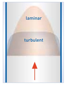
Figure 9.3: Three-dimensional flow profile
Flow profile
The velocity distribution of the flow of liquids in closed pipelines is not constant across the pipe. Under ideal conditions, the closer you get to the “middle” of the pipe, the greater the flow velocity. The closer you get to the wall of the pipe, the slower the flow. The velocity distribution can be illustrated two-dimensionally or three-dimensionally across the pipe. This is called a velocity or flow profile. Figure 9.2 shows a two-dimensional, Figure 9.3 a three-dimensional laminar and turbulent flow. If you have an extremely long, straight pipeline, two different flow profiles are formed, depending on the diameter of the pipe, flow velocity and viscosity: either a laminar or a turbulent flow profile. The turbulent flow profile is “flatter” than the laminar one. These flow profiles are called swirl-free and rotationally symmetric. To achieve the desired measuring accuracy, the unimpeded inlet run required in front of a flowmeter depends on the measuring principle used (EMF, Vortex, ultrasonic, Coriolis etc.).
Installation situation
In terms of pipe direction the practical installation of a flowmeter in an application is always bound to onsite possibilities. Often, having system parts that change the flow profile located close to the measuring devices cannot be avoided. This includes built-ins like 90°elbows, 3D bends, shut-off devices, reducers and expansions, filters etc. Information regarding which combinations or built-ins and measuring devices are to be avoided can be found in the technical documentation of each measuring device.
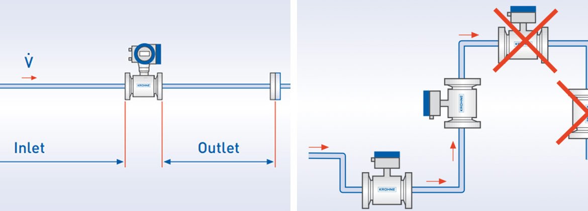
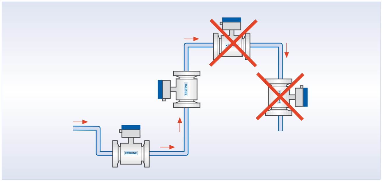
Figures 9.4 and 9.5 show examples from documentation with recommended flowmeter installation sites and those sites to avoid.
If there are built-ins in the pipeline, changes such as one-sided increases in velocity or swirling components in the local flow can be the consequence. These changes are slow to be diminished in the straight pipeline until finally a rotationally symmetric, distinct laminar or turbulent flow profile is restored. To counteract such interference with the measuring accuracy of the flowmeter, the data sheets for the respective flowmeters indicate minimum inlet sections based on the desired measuring accuracy. In general, it can be said that longer inlet runs diminish the influence of flow interferences.
Figure 9.4: Installation notes for electromagnetic flowmeters
Figure 9.5: Installation notes for electromagnetic flowmeters
Calibration conditions
Flowmeter calibration generally occurs at defined pressure, temperature and ambient conditions. Changes in these conditions when using the measuring device in practice can result in more or less serious changes in the measured value. Nowadays, flowmeters such as variable area flowmeters, are sometimes designed for use in a specifically defined parameter range. Here, no corrections need be taken into account on site. If the influence of the parameter is significant, a correction may be made with the appropriate measurement of pressure and temperature (pressure and temperature compensation with vortex flowmeters). Significant meaning is thus attached to the”Quality” used for potential conversions of the material parameters used as data with significant measurement uncertainty have a direct impact on the result of the measurement.
As a general rule, flowmeters are calibrated using water or air. Operating points which in terms of density, temperature, viscosity etc. deviate from the calibration conditions, can be taken into account mathematically if necessary. In order to perform measurements with minimal uncertainty, some circumstances may require that calibration be done with the original liquid or original gas (true gas calibration).
Repeatability / reproducibility
To guarantee process conditions with a high degree of stability, flowmeters with high repeatability are required, i.e. the measuring device should also output the same measured values with minimal scattering, regardless of the absolute accuracy of the individual values under the same operating conditions in realtime. Data about the repeatability of a measuring device can only be collected under repeatability condition of measurement. This includes such things as constant temperatures, pressures, humidity, observers, measurements following one another at close intervals and the same reference. Multiple measurements on a test rig can be used as data for repeatability. In the absence of quantitatively useful calculation specifications in the area of liquid measurements, it is often the smallest and largest values that are used but these are not statistically meaningful and do not allow for a comparison of information. A recommendation for the quantitative determination of repeatability can be found in [7]. The terms generally used for this in the literature are “repeatability” or “reproducibility”. In contrast to that there is advanced reproducibility which takes into account different observers, installation sites and changed process and ambient conditions. As for repeatability there is no known calculation specification for liquids for the specification of a quantitative value.
Long term stability
If a measuring device is observed in use over a longer period of time, the measurement should not drift at all under constant conditions. If the measurement errors caused by any aging, drift or environmental influences is negligible over a longer period of time, the measuring device is said to have high long-term stability.
Influences in practical use
When you consider the calibration values of a flowmeter, ideally they should not deviate from the measuring values in the application.
References and measurement standards
Calibration usually takes place with the help of a “more accurate” measuring device. This device is referred to as the reference, the measurement standard or superior measurement standard.
Calibrations at KROHNE
KROHNE has calibration options for all kind of measuring devices at different locations worldwide.


